

Engine and Transmission Tech
tips, technology, tools and techniques related to vehicle driveline components
|
Moderator Curtis Jacobson Portland Oregon (4577 posts) Registered: 10/12/2007 02:16AM Main British Car: 71 MGBGT, Buick 215 |
Re: custom plenum and fuel rail on Rover EFI manifold
I mailed them out Saturday and hope to have them back tomorrow. When they arrive, I'll scan and post the test report.
Quote: |
|
BlownMGB-V8 Jim Blackwood 9406 Gunpowder Rd., Florence, KY 41042 (6470 posts) Registered: 10/23/2007 12:59PM Main British Car: 1971 MGB Blown,Injected,Intercooled Buick 340/AA80E/JagIRS |
Re: custom plenum and fuel rail on Rover EFI manifold
OK, so I would guess that maybe the mention of the dynamic tests that they run would be the cycling test which would apply to part throttle conditions. To my mind the partial flow is every bit as critical as full saturation flow. In fact, if the injectors are correctly sized they will never quite reach full saturation and will always be operating in the cycling mode, which means the pulse width is turning them on and off continuously with the pulse duration controlling the length of time they are switched on, thereby controlling the amount of fuel that is delivered.
In all probability your injectors perform uniformly in the cycling mode. However, I have seen sets of injectors that did not and in fact I have a set on the bench right now that preliminary tests indicated horrendous variations even though the full flow is pretty uniform. Hopefully a good cleaning will straighten them out but my fear is that the vendor may have made up a set of 8 by combining 2 sets of 4 from different engines and they may be quite different in their fuel delivery curves. A good cleaning followed by the cycling test should tell the tale. Generating a fuel delivery curve is a good deal of work. You have to determine the flow rate at each point in the graph, which means a timed test and a fuel measurement for each injector. So for eight injectors and just a four point graph which is very rough, you have 32 measurements to make and enter into a program to generate the 8 individual curves, one for each injector. It also means having an injector driver that can deliver the appropriate pulses to all 8 injectors at the same time and is set up to allow you to select the right pulse width. That's a pretty sophisticated flow bench. Mine has the capability to do full saturation and a cycling test that gives about 1/4 to 1/3 full flow, although I really don't know what the pulse width is. The next upgrade will have selectable pulse widths, possibly with a digital pulse width readout but I won't be needing that right away. The cycling test does a pretty good job for now, and I can get back to improving that once my car is a little closer to being driveable. OTOH, if I happen across a digital display that can give a pulse width measurement I just might have to do the upgrade. This is the one I'm using for the test interval: [www.ebay.com] Maybe they have one that can read in the millisecond range. Injector pulses run from about 2 milliseconds up to about 28 typically. It takes at least 1-2 ms for the injector to open (disc type injectors are a little faster so they have a little better dynamic range... at the cost of lower maximum flow capability but perfect for a 3.5) and beyond 28 ms we run out of injector time at high rpm. Once that happens no more fuel can be added without increasing rail pressure. Curtis, you definitely did the right thing having your injectors cleaned and tested. The test results show that very clearly. Jim |

|
|
Moderator Curtis Jacobson Portland Oregon (4577 posts) Registered: 10/12/2007 02:16AM Main British Car: 71 MGBGT, Buick 215 |
Re: custom plenum and fuel rail on Rover EFI manifold
I have injectors off of two different Rover engines. They're all nominally "Lucas" injectors, but actually only one set has Lucas logos molded into them and the other set has Seimens logos. The Lucas ones had green stripes painted around their middle, whereas the Siemens injectors were all black except for a green plastic clip near the top. Exterior shape/dimensions were identical. Some of the Lucas injectors were banged up, so I had the Seimans injectors cleaned (plus one of the Lucas injectors as a spare.) What I think I've learned from your post, Jim, is that I shouldn't mix the two brands on my engine, even though they all flow 58cc/15s wide open because they might not all flow the same at partial throttle. Cool.
|
|
Moderator Curtis Jacobson Portland Oregon (4577 posts) Registered: 10/12/2007 02:16AM Main British Car: 71 MGBGT, Buick 215 |
Re: custom plenum and fuel rail on Rover EFI manifold
Next issue... how to "optimize" the length of the trumpets. The flared steel tubes all start out 100mm long. Rover installed them into recesses of two different depths... so the trumpets for cylinders 4,5,6,&7 appeared longer:
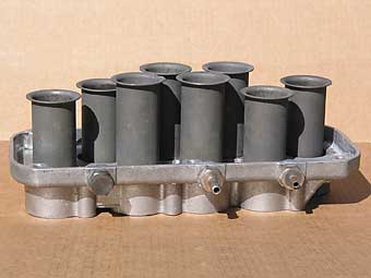
Why? Apparently to crudely equalize overall intake port length. Note how some ports in the intake manifold are longer than others because they cross over... 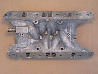
The bottoms of my trumpets are flat against my Rover intake manifold, and my plan for some time has been to trim some of them. The longest trumpet(s) will be left 100mm. Some time ago, I crudely shaped lengths of copper wire to follow the approximate center-line of each port and then I straightened and measured the wires. Based on that exercise, I expect the trumpets for cylinders 1 and 8 should end up ~55mm long and the trumpets for cylinders 2 and 7 will end up ~75mm long. Would it be better to "cc" the ports instead, and equalize volume instead of length? I don't have an extra set of Rover 4.0 heads around, so it's not convenient to cc their intake-side ports. Anyone know where to get cc numbers for them? (I guess I could cc my spare set of Buick 215 heads...) Suggestions? Opinions? |
|
BlownMGB-V8 Jim Blackwood 9406 Gunpowder Rd., Florence, KY 41042 (6470 posts) Registered: 10/23/2007 12:59PM Main British Car: 1971 MGB Blown,Injected,Intercooled Buick 340/AA80E/JagIRS |
Re: custom plenum and fuel rail on Rover EFI manifold
Curtis, the runners are very likely to be different lengths and also different volumes. The ports in the head should be pretty close to equal volume although some minor variation is likely. So your task is basically to equalize the overall volume of the ports and runners by trimming the trumpets. You should be OK in disregarding the ports when you do this but if you can check with Dan Jones he will have the exact answers you are looking for since he has done a lot of port work on these heads.
Sticking with the full set of injectors is the safest approach, short of more thorough testing and I think you will be fine doing that. Your flow test after cleaning gives sterling numbers and there is no reason to think partial flow would show any more spread. But when you start tuning just remember that it can happen and be aware of any inconsistencies from one side to the other. Jim |
|
ex-tyke Graham Creswick Chatham, Ontario, Canada (1165 posts) Registered: 10/25/2007 11:17AM Main British Car: 1976 MGB Ford 302 |
Re: custom plenum and fuel rail on Rover EFI manifold
Equalizing port/runner volumes wouldn't necessarily guarantee equal flow. If you're trying to qualify equal intake runner flow, wouldn't a flow bench test be you're best bet?....ie tune the trumpets for equal flow.
|
|
|
|
BlownMGB-V8 Jim Blackwood 9406 Gunpowder Rd., Florence, KY 41042 (6470 posts) Registered: 10/23/2007 12:59PM Main British Car: 1971 MGB Blown,Injected,Intercooled Buick 340/AA80E/JagIRS |
Re: custom plenum and fuel rail on Rover EFI manifold
That would be ideal, if he could get set up with the same head he is using. Same valves would be even better. A change in the bell shape can also vary the flow, and it should be tuned at different flow rates to see if they can be equalized under part throttle conditions. He already has some pretty good tri-Y headers so exhaust flow should be pretty close to equal. Curtis, I think once you are finished with this you are going to be pleasantly surprised with the output of this engine.
Jim |
|
Moderator Curtis Jacobson Portland Oregon (4577 posts) Registered: 10/12/2007 02:16AM Main British Car: 71 MGBGT, Buick 215 |
Re: custom plenum and fuel rail on Rover EFI manifold
I'm definitely a neophyte in all this... but my impression is that a flow bench is the right tool for optimizing and equalizing max flow rate but isn't all that useful for working out Helmholtz (pressure wave) resonance effects. (As the intake valve opens and closes very rapidly, pulses of pressure run through the air column in the intake track...) Am I right in that assessment? I certainly do wish I had access to a flow bench, and to someone who could show me how to use it! I'm sure it would be helpful, but I suspect it would only help with part of the puzzle.
My plenum top will be held on by just two cap screws, I have an extra set of Rover trumpets, and Rover trumpets are only ever held in by friction... so trial-and-error dyno testing is feasible. It would for example be easy to do a quick-and-dirty A-B comparison between staggered (equalized port volume) and max-length (100mm) trumpets in consecutive rolling-road dyno pulls. If conventional theories hold true, staggered trumpets should produce a higher peak torque whereas max-length trumpets might produce a flatter curve with peak torque at a lower engine speed. My machinist friend and I have talked about spinning some full radius trumpets out of aluminum tube. I enjoy few things more than learning new manufacturing processes! If there's a ready market for them and if I could take some pre-orders... |
|
mgb260 Jim Nichols Sequim,WA (2463 posts) Registered: 02/29/2008 08:29PM Main British Car: 1973 MGB roadster 260 Ford V8 |
Re: custom plenum and fuel rail on Rover EFI manifold
Curtis, Bill on the SAOCA used equal length runners on a homemade intake. Shorter length moved powerband up,longer length helped low end torque.
|
|
BlownMGB-V8 Jim Blackwood 9406 Gunpowder Rd., Florence, KY 41042 (6470 posts) Registered: 10/23/2007 12:59PM Main British Car: 1971 MGB Blown,Injected,Intercooled Buick 340/AA80E/JagIRS |
Re: custom plenum and fuel rail on Rover EFI manifold
Yeah, they had those BBC's (Can AM maybe) with the staggered length runners supposedly to broaden the torque curve? Seems I heard something about that.
Maybe as much worth considering as trumpet length is proximity. What I mean is those runners nearest in the firing order really should be separated in physical location. #5 and 7 are usually the biggest concern but where the runners come together in the center like these do the 4&3 pair and the 6&5 pair might be considered as well. The problem is one cylinder stealing the charge from the adjacent one and it was a real problem in the early flathead V8 engines, leading to extremely and unexpectedly low power outputs until the dual plane type intakes were developed, which explains where this seemingly odd V8 design came from. I do not really know how severe the problem is with EFI where you are not dealing with the fuel but the cylinder is sucking in air for close to 180 degrees and the runners are 90 degrees apart so it is at least worth looking at where the runners come out to see how much separation there is on those three pairs. I've never done this and I would expect them to be optimized but I've been surprised before. On the resonances, again there will be some interplay between the runners and without having the valves slamming shut there is no way to evaluate it that I know of. Sometimes with IR intakes you could see liquid fuel at the top of the throttle bores where it had been carried by the reversion but without some extremely elaborate test equipment I'm not sure how you would measure this. Possibly some sort of orifice equipped accumulating manometer sensitive enough to measure a decrease in pressure in the runner, or possibly a differential from one end to the other. It would seem that a larger than average differential would indicate reversion. But then the question is, how much difference does it make and then what can be done about it? Without more information I don't have any answers for that. Jim |
|
|
|
Moderator Curtis Jacobson Portland Oregon (4577 posts) Registered: 10/12/2007 02:16AM Main British Car: 71 MGBGT, Buick 215 |
Re: custom plenum and fuel rail on Rover EFI manifold
Quote: I can't say enough about how pleased I am with the job Peterson Fluid Systems did on the welding. Of course their main business is dry sump oil pumps, tanks, breathers, filters, lines, fittings, and other lubrication system components... but they're happy to take occasional welding odd-jobs too. Give them a call. 
(Did I mention that they're a BritishRacecar.com advertiser? Tell them I sent you!) |
|
Moderator Curtis Jacobson Portland Oregon (4577 posts) Registered: 10/12/2007 02:16AM Main British Car: 71 MGBGT, Buick 215 |
Re: custom plenum and fuel rail on Rover EFI manifold
Something else to report: I did a little cc'ing this morning to satisfy my curiosity. I only had rudimentary tools at hand but I measured everything twice and seemed to get consistent results.
The four intake ports on a spare Buick 215 head are indeed very nearly identical in volume. The number I got was ~90cc each. The Rover EFI manifold really is symmetrical. Mine has been decked 1/2" on top. I measured: cylinders #1 and #8 ==> ~190cc, #2 and #7 ==> ~160cc, #3, #4, #5 & #6 ==> ~130cc. The volume of a stock (100mm) trumpet is easy to calculate: just barely over 114cc. Thus, if I trim trumpets to equalize volume, the four in the middle will end up ~25mm longer than the ones for cylinders #2 and #7 and ~50mm longer than the ones for cylinders #1 and #8. |
|
Moderator Curtis Jacobson Portland Oregon (4577 posts) Registered: 10/12/2007 02:16AM Main British Car: 71 MGBGT, Buick 215 |
Re: custom plenum and fuel rail on Rover EFI manifold
Now we have a very stout and tight fitting plenum lid. Scott McRoberts does handsome work, doesn't he! The photo above is just a trial installation. Tomorrow we'll radius the lid's outer edge. I'm not sure if we'll stop with that or machine-in a little bit more detail. I expect the lid will ultimately be powdercoated satin black to match the valve covers. |
|
rficalora Rob Ficalora Willis, TX (2764 posts) Registered: 10/24/2007 02:46PM Main British Car: '76 MGB w/CB front, Sebring rear, early metal dash Ford 302 |
Re: custom plenum and fuel rail on Rover EFI manifold
If it works as good as it looks you'll be taking orders before you know it!
|
|
|
|
BlownMGB-V8 Jim Blackwood 9406 Gunpowder Rd., Florence, KY 41042 (6470 posts) Registered: 10/23/2007 12:59PM Main British Car: 1971 MGB Blown,Injected,Intercooled Buick 340/AA80E/JagIRS |
Re: custom plenum and fuel rail on Rover EFI manifold
That's pretty sharp Curtis. What does your clearance over your trumpets look like?
Jim |
|
Moderator Curtis Jacobson Portland Oregon (4577 posts) Registered: 10/12/2007 02:16AM Main British Car: 71 MGBGT, Buick 215 |
Re: custom plenum and fuel rail on Rover EFI manifold
Thanks, guys!
We finished the lid this morning. After sleeping on it, I decided to cut a shallow 3/4" racing stripe down the top from front to rear, off-center to driver's side like the big white stripe on my roof. We flipped the cover over and cut out the bottom so it's 1/8" thick through the center. So my next question is: "How much clearance between trumpets and lid do I need?" The front edge of cylinder number three's trumpet will be closest. Without trimming it's only got about 3/8" clearance. That probably isn't enough, so each trumpet will need trimming after all. Maybe 3/8" off each? (More get trimmed on #'s 1,2,7,&8 to equalize runner volumes, per previous posts.) For a reality check, I pulled out a Rover 3.9 plenum and measured its trumpet clearances. Stock, they had ~0.45" for cylinders 2&7, and ~0.55" for cylinders 3&5. |
|
BlownMGB-V8 Jim Blackwood 9406 Gunpowder Rd., Florence, KY 41042 (6470 posts) Registered: 10/23/2007 12:59PM Main British Car: 1971 MGB Blown,Injected,Intercooled Buick 340/AA80E/JagIRS |
Re: custom plenum and fuel rail on Rover EFI manifold
Best way to determine that would be with a flow bench and the lid is going to affect #3 somewhat. You could probably trim it a bit more than the others. The torroid formed between the lip of the bell mouth and the lid effectively extends the length of the tube, provided the cross section is correct. What you can do is determine the area of the cylinder from the lip up to the lid (taking into account the lid angle) and compare that to the area at the max diameter of the flare. Where the two match is going to be real close to the smoothest transition at minimum height, or maximum length of the tube. The angle will probably throw the calculations off a little but at least it'll get you close. See how that matches up to the Rover spec.
Jim |
|
Moderator Curtis Jacobson Portland Oregon (4577 posts) Registered: 10/12/2007 02:16AM Main British Car: 71 MGBGT, Buick 215 |
Re: custom plenum and fuel rail on Rover EFI manifold
Newer photos:
(decided to add a "racing stripe") (Rover intake manifold with thermostat bypass relocated to align with Buick front cover) |
|
|
Sorry, only registered users may post in this forum.
British V8 Home Page
Photo Gallery
Web Forum
Annual Meetings
Contact Info
Site Map
British Race Car

© 2019 British V8™ All rights reserved. Website & graphic design by:
Curtis Jacobson.
BritishV8 Forum is hosted by
SiteWelder LLC,
and is powered by a
Phorum engine.