

Steering, Suspension, & Brakes
tips, technology, tools and techniques related to non-driveline mechanical components
|
Bill Young Bill Young Kansas City, MO (1337 posts) Registered: 10/23/2007 09:23AM Main British Car: '73 MG Midget V6 , '59 MGA I6 2.8 GM, 4.0 Jeep |
Re: A-arm spacers
Jim, to overcome the problem of the rather wide spaced mounting ears on the stock MGB part, perhaps you could find something from another car that would fit and have the more standard two bolt mount of a lot of American car upper A arms or even machine one from some bar stock.
|
|
BlownMGB-V8 Jim Blackwood 9406 Gunpowder Rd., Florence, KY 41042 (6569 posts) Registered: 10/23/2007 12:59PM Main British Car: 1971 MGB Blown,Injected,Intercooled Buick 340/AA80E/JagIRS |
Re: A-arm spacers
Results are in. With the new blocks and with the car at about standard ride height the camber is right at zero, depending on where ride height is set. Under compression there is a gradual increase, for a total of maybe an extra half a degree or slightly more positive. But at full droop there is about 2 degrees negative camber. I'm afraid I did not check the specs with the stock mounting so I really can't say how much change there has been. Regardless, the car should be OK with these settings I think, I really won't know until I drive it. Caster is down in the 2-3 degree range, (my suspension angle measuring equipment isn't super accurate) and if this car had standard width tires I'd suspect, based on reports I've heard, that wheel return to center would be weak or non-existent. With the wider tires it will hopefully be acceptable. In any case the steering effort should be markedly reduced.
I'm not sure exactly what the angle of inclination of the kingpin plays in all of this... might be worth investigating. And I have good clearance to the steering rack. JB |
|
mgb260 Jim Nichols Sequim,WA (2631 posts) Registered: 02/29/2008 08:29PM Main British Car: 1973 MGB roadster 260 Ford V8 |
Re: A-arm spacers
Jim, I think you want negative under compression and positive at droop.Also remember with the car on the ground,is the lower arm parrallel with tie rod to eliminate bump steer.Also you want a minimum of 4 degrees caster for the steering wheel to self center. Just trying to help.
Edited 1 time(s). Last edit at 11/23/2010 04:20PM by mgb260. |

|
|
DiDueColpi Fred Key West coast - Canada (1389 posts) Registered: 05/14/2010 03:06AM Main British Car: I really thought that I'd be an action figure by now! |
Re: A-arm spacers
Hey Jim,
Nice work on the blocks. What if you pie cut them so that the control arm mounting ears are parallel to the ground? Slot them with "T" bolts and you can adjust the caster and camber to whatever you want. You could then make them the same dimension and eliminate the angle induced into your lower arm. I think that this angle is going to cause trouble with caster gain under compression. The lower arm will move forward as it goes up and the upper arm won't. The outside wheel is going to gain caster and the inner will lose some. This will cause the car to want to turn harder as you turn in. May be a non issue but I thought that I should bring it up. Cheers Fred |
|
BlownMGB-V8 Jim Blackwood 9406 Gunpowder Rd., Florence, KY 41042 (6569 posts) Registered: 10/23/2007 12:59PM Main British Car: 1971 MGB Blown,Injected,Intercooled Buick 340/AA80E/JagIRS |
Re: A-arm spacers
Thanks for the comments, some of those things I hadn't considered. Well, first let me say that the blocks haven't got any relation to the air bags, as the only reason they are there in the first place is because of the lowered steering rack. We didn't have to do any of this on the MG-Roadmaster, obviously we didn't lower the rack as far, so ultimately I may revisit the rack mounts and then have another look at things. But the air bags are a drop in swap for the coil springs. I'm going to try to order another set of them tomorrow, in case anyone wants to give them a try. It looks like about 80 psi should be the operating pressure.
At any rate, a lot was learned about the suspension by doing this and if I relocate the rack I'll take measurements with the stock mounts to see what the car normally does. But I do think there is some advantage to be had with decreasing the caster, just maybe not quite so much. What would be real helpful at this point is some sort of a suspension program that will allow the pivot points and arm lengths and such to be varied and show the results. Preferably a shareware program, and preferably one that will allow the use of kingpins. JB |
|
BlownMGB-V8 Jim Blackwood 9406 Gunpowder Rd., Florence, KY 41042 (6569 posts) Registered: 10/23/2007 12:59PM Main British Car: 1971 MGB Blown,Injected,Intercooled Buick 340/AA80E/JagIRS |
Re: A-arm spacers
I had a thought last night. The angle front to rear of the LCA may cause caster changes as Fred mentions (causing the outer wheel to want to return to straight more than the inside one?) but that is also the mechanism that causes anti-dive (exactly how I still don't completely appreciate). Here the angle is slight and should only provide a small amount of anti-dive but I have heard of percentages in the 20's. I may eventually figure out how to calculate it, but based on that it looks like another of those infamous trade offs.
Before the mod, my car had a tremendous amount of caster induced steering return, enough to yank the wheel out of my hands on the autocross course and friction burn my wrist. I think that is a little excessive, but how much reduction is enough is another question entirely. But if 4* is right for a standard MGB I'd guess that half of that wouldn't be too little. Remember, we're talking about a very wide tire here, formerly a 265/50-14 and probably to be replaced with a 265/40-17, so 9-1/2" of tread width. That makes a real big difference in steering return. Now something we've not taken into account is roll induced camber change, which I think will induce more positive camber on the outside wheel, although it will also induce more negative camber on the inside wheel. Sounds like I may want to try to control that, or else come up with a different design change. Anyone have a favorite suspension program to recommend? JB |
|
Bill Young Bill Young Kansas City, MO (1337 posts) Registered: 10/23/2007 09:23AM Main British Car: '73 MG Midget V6 , '59 MGA I6 2.8 GM, 4.0 Jeep |
Re: A-arm spacers
Jim, this blurb from Wikipedia might help you figure out the anti dive.
In most cars it's engineered in by tilting the upper control arm more down at the rear leaving the lower control arms basically parallel to the ground. You're doing the opposite so I'm not sure how it would affect the handling. In very simple terms I always thought that it was similar to how we used to design traction bars back in the 60s. If the bar contacted the chassis to the rear of the center of gravity it would tend to lift the rear of the car on acceleration, if it was forward of the center of gravity it would tend to lift the front. Anti dive was similar in the front. If you draw a line through the pivot points of the upper and lower control arm and the intersection fell in front of the center of gravity you had a lot of anti dive, if it didn't intersect withing the wheelbase then you basically had none, and if it intersected to the rear of the center of gravity you got a lot of dive as it would tend to lift the rear. That was my take on it. No slide rule math, just seat of the pants type intuition. Right now with your spacers I'd think that the line would intersect towards the rear and cause the rear of the car to lift on braking. Anti-dive and anti-squat Anti-dive and anti-squat are expressed in terms of percentage and refer to the front diving under braking and the rear squatting under acceleration. They can be thought of as the counterparts for braking and acceleration as jacking forces are to cornering. The main reason for the difference is due to the different design goals between front and rear suspension, whereas suspension is usually symmetrical between the left and right of the vehicle. To determine the percentage of front suspension braking anti-dive, it is first necessary to determine the tangent of the angle between a line drawn, in side view, through the front tire patch and the front suspension instant center, and the horizontal. Then, divide this tangent by the ratio of the center of gravity height to the wheelbase. Finally, multiply by 100. A value of 50% would mean that half of the weight transfer to the front wheels, during braking, is being transmitted through the front suspension linkage and half is being transmitted through the front suspension springs. Forward acceleration anti-squat is calculated in a similar manner and with the same relationship between percentage and weight transfer. Anti-squat values of 100% and more are commonly used in dragracing, but values of 50% or less are more common in cars which have to undergo severe braking. Higher values of anti-squat commonly cause wheel hop during braking. It is important to note that, while the value of 100%...in either case...means that all of the weight transfer is being carried through the suspension linkage, this does not mean that the suspension is incapable of carrying additional loads (aerodynamic, cornering, etc.) during an episode of braking or forward acceleration. In other words, no "binding" of the suspension is to be implied. |
|
|
|
BlownMGB-V8 Jim Blackwood 9406 Gunpowder Rd., Florence, KY 41042 (6569 posts) Registered: 10/23/2007 12:59PM Main British Car: 1971 MGB Blown,Injected,Intercooled Buick 340/AA80E/JagIRS |
Re: A-arm spacers
You're making my head hurt.
JB |
|
DiDueColpi Fred Key West coast - Canada (1389 posts) Registered: 05/14/2010 03:06AM Main British Car: I really thought that I'd be an action figure by now! |
Re: A-arm spacers
Bill,
So does my bottle of scotch need more anti dive or anti squat? Fred. |
|
Moderator Curtis Jacobson Portland Oregon (4636 posts) Registered: 10/12/2007 02:16AM Main British Car: 71 MGBGT, Buick 215 |
Re: A-arm spacers
This article from BritishRaceCar.com also explains and illustrates anti-dive (and anti-squat):
Paul Dudiak's McKee Mk12 Formula 5000 Racecar 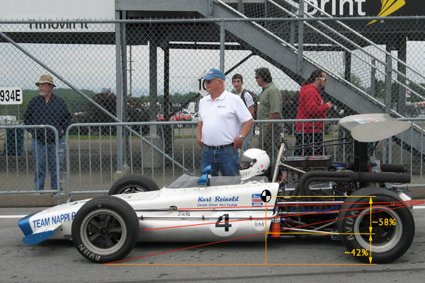
Part of the explanation is here: Quote: Edited 1 time(s). Last edit at 11/24/2010 08:41PM by Moderator. |
|
|
|
roverman Art Gertz Winchester, CA. (3188 posts) Registered: 04/24/2009 11:02AM Main British Car: 74' Jensen Healy, 79 Huff. GT 1, 74 MGB Lotus 907,2L |
Re: A-arm spacers/anti-squat racers
Interestingly enough, C5 Corvette, LCA inner pivot is"lower" at front ! As you might guess, this accentuates anti dive and roll castor gain. Static caster is +7.4deg +/- .5deg. camber is -.20, +/- .5 deg. This works with FAT tires, up front, because of "manditory" power rack steering. I suspect those "sneaky", suspension engineers, want more wheel base on outside of turn,(cone effect/reduced slip angle), somewhat similar to"tire stagger" the oval people use, only without the "drag" on the straight-aways.This being installed in my 69' AMX, should prove to handle better, than the average Rambler.roverman.
|
|
BlownMGB-V8 Jim Blackwood 9406 Gunpowder Rd., Florence, KY 41042 (6569 posts) Registered: 10/23/2007 12:59PM Main British Car: 1971 MGB Blown,Injected,Intercooled Buick 340/AA80E/JagIRS |
Re: A-arm spacers
Wasn't sure where I had the info on the air springs, but Good News Everyone! I finally found all the parts needed for the compressor kit and got everything ordered. Another week or so and all the parts should be here so I should have no trouble getting a kit together for the V8 meet. It will contain the following:
2-airbags (with centering cup and push air fittings) 1-300psi compressor (w/ 3 way cushion mounts and push fitting) 1-150psi dashboard gauge (Equis w/ push fitting) 1-bleed valve (Clippard, brass button w/ push fitting) 1-pushbutton (red w/ chrome trim ring, 5/8" hole, 1/4" spade) 3-"Y" push(insert)-to-connect line fittings 15ft-1/8" plastic air line I've made assembly as easy and convenient as I can. Installation will involve removal of the old spring and clean up, I recommend trimming the little tab out of the way with an angle grinder for bag clearance, and if you'd like to route the air lines up out of the way you'll need to drill one or two ~1/4" holes in each spring pan and fit some rubber hose over the tubing for chafing resistance where it goes through them. Everything is just trim and insert (all air fittings are insert and push-to-connect), find a location for the compressor and drill two 5/32" holes to mount it, locate where you want the gauge and buttons, and then a little wiring for power and the switch. A Saturday morning should be all you need to get it done. Why? Well once you're finished you can control ride height from the driver's seat. Got a problem scraping when you enter the driveway? Pump up the pressure and roll right in, let it back down when you leave. Want to lower the nose a little for a stretch of twisty road? Hit the bleed and drop it down. Plus it's sure to ride nicer with the air springs. What I'll probably do is bring the complete kit to show and tell at the meet and take orders, plus whoever is first can buy this one and take it home when the meet is over. I'll repost in a new thread with all the details and pictures once all the parts get here. JB |
|
rficalora Rob Ficalora Willis, TX (2764 posts) Registered: 10/24/2007 02:46PM Main British Car: '76 MGB w/CB front, Sebring rear, early metal dash Ford 302 |
Re: A-arm spacers
Will be interesting to see Jim -- I'm particularly interested in seeing wether it'd be viable & if so what would be involved in adapting to replace a coil over set up like I currently have.
|
|
BlownMGB-V8 Jim Blackwood 9406 Gunpowder Rd., Florence, KY 41042 (6569 posts) Registered: 10/23/2007 12:59PM Main British Car: 1971 MGB Blown,Injected,Intercooled Buick 340/AA80E/JagIRS |
Re: A-arm spacers
Here's how the hose should be routed. As you can see it is well protected, tucked up out of harm's way and insulated by rubber hose where it might rub. Found a good spot for the compressor up in the rear corner of the engine bay.
I also redid the steering rack mounts, moving them up and forward a bit. Everything should clear nicely now, whether I use the spacer blocks or not, and there is adequate clearance to the engine. However, the straight oil filter mount will no longer work so I will have to find one from a V6 or some other SBB variety which is angled forward. I will also need to tweak the steering arms again to get them back in line with the rack. JB |
|
|
Sorry, only registered users may post in this forum.
British V8 Home Page
Photo Gallery
Web Forum
Annual Meetings
Contact Info
Site Map
British Race Car

© 2025 British V8™ All rights reserved. Website & graphic design by:
Curtis Jacobson.
BritishV8 Forum is hosted by
SiteWelder LLC,
and is powered by a
Phorum engine.