

Steering, Suspension, & Brakes
tips, technology, tools and techniques related to non-driveline mechanical components
|
roverman Art Gertz Winchester, CA. (3188 posts) Registered: 04/24/2009 11:02AM Main British Car: 74' Jensen Healy, 79 Huff. GT 1, 74 MGB Lotus 907,2L |
straighline TR8 suspension
Race car has a 3 bar set-up with a long panhard bar. How to get maximum forward/straight bite,(1/4 mile at a time). Something to do with aiming the 3 links at the CG ? Will possibly need wheelie bars. Light rate springs on the front with light /adjustable "extension rate" on adjustable strut inserts ? Skilled suggestions please ? Thanks, art.
|
|
MGBV8 Carl Floyd Kingsport, TN (4629 posts) Registered: 10/23/2007 11:32PM Main British Car: 1979 MGB Buick 215 |
Re: straighline TR8 suspension
I have been pondering 3-links for years, Art. I have gained some knowledge & collected a good bit of info.
Are your upper & lower 3-links adjustable? BTW, 1/4 mile at a time is waaaay too short of an adrenaline rush for standing around for hours waiting your turn. Is there any one mile racing anywhere close? |
|
roverman Art Gertz Winchester, CA. (3188 posts) Registered: 04/24/2009 11:02AM Main British Car: 74' Jensen Healy, 79 Huff. GT 1, 74 MGB Lotus 907,2L |
Re: straighline TR8 suspension
Huffaker built, about 6-8 positions on upper/lowers. Adjustable coil-overs on rear. I would like to sneak-up, on wheelie potential, to determine if wheelie bars are needed ? 1/8 mile drags for shake-downs and prove auto trans,(3.9/1) r&p. .75/1 in od. One mile, standing start,races at Apple Valley Airport, close enough. I have a bubble nose piece and
maybe pull front/rear windows.... Maybe old guy get jollies ? art. |

|
|
MGBV8 Carl Floyd Kingsport, TN (4629 posts) Registered: 10/23/2007 11:32PM Main British Car: 1979 MGB Buick 215 |
Re: straighline TR8 suspension
Of course, 4-links are better suited than the 3-links for all out drag racing. I have read that the panhard rod on a 3-link can adversely affect traction, as well.
In a nutshell, my understanding is the lower links are used to tune for rear steer & the top link adjusts anti-squat. More anti-squat is what you are looking for. I would start with all three bars parallel to the ground. Angling the upper control bar/link downward toward the front of the car will increase anti-squat. So, upper link downward a few degrees or even lower links up. I have read where some street/strip drag racers drop the lower links one hole at the rearend for strip, then move back to level for street. Pulling wheelies would indicate too much anti-squat & not enough forward push. From my reference notes: ----------------------------------------------------------- All rear end linkage tuning is based around 3 simple strategies: 1. Where am I lifting 2. How much housing torque is distributed to lifting the car? 3. How much housing torque is distributed to pushing the car forward? 1. Where youre lifting is normally the IC in most suspensions, except in a torque arm, where it is the attachment point. The shorter you make the swing arm, the quicker & harder it will load the tires, but with less weight & for a shorter period. The longer the swing arm, the slower & softer it will load the tires, but with more weight & for a longer period. 2 & 3. The location & angle of the links and location of the pivots define how much of the housing torque is distributed to lifting the car & how much is distributed to pushing the car forward. You can not change one without affecting the other. More torque distributed to lift plants the tires quicker & harder leaving less torque to push the car forward. Less torque distributed to lift plants the tires slower & softer leaving more torque to push the car forward. These sound similar, but 1 is different from 2 & 3. Where you lift does not necessarily define torque distribution. It does define how much weight of the car can be used to load the tires. This can be a little cloudy, but I think it will be clear & simple when you see how to tune it with a 3 or 4 link. With high powered cars, I usually set the IC under the CG as a starting point so I have the full weight of the car to load the tires then I work out the torque optimum distribution from the housing for chassis lift & forward push. Here is how to tune it More lift/less forward push: A. Increase distance of top link housing mount pivot above the axle CL B. Increase distance of top link housing mount pivot behind the axle housing CL C. Decrease distance of lower link housing mount pivot below the axle CL D. Increase distance of lower link pivot in front of the axle housing CL E. Increase the distance of the lower link chassis mount pivot in front of the axle housing CL compared to top link chassis mount pivot in front of the axle housing CL F. Increase downward angle of top links G. Increase upward angle of lower links A, B, D & E: Can be achieved without affecting the IC arm lift point, if built into the design. C: Has a minor shortening effect on the IC arm lift point & raising the IC. F: Shortens the IC arm lift point significantly and has no impact on rear steer. G: Shortens the IC arm lift point significantly BUT adds positive rear steer. Only do this if positive rear steer effect is desired too. Less lift/more forward push: H. Decrease distance of top link housing mount pivot above the axle CL I. Increase distance of top link housing mount pivot in front of the axle housing CL J. Increase distance of lower link housing mount pivot below the axle CL K. Increase distance of lower links behind the axle housing CL L. Decrease the distance of the lower link chassis mount pivot in front of the axle housing CL compared to top link chassis mount pivot in front of the axle housing CL M. Decrease downward angle of top links N. Increase downward angle of lower links H, I, K & L: Can be achieved without affecting the IC arm lift point, if built into the design. J: Has a minor lengthening effect on the IC arm lift point & lowering the IC. M: Lengthens the IC arm lift point significantly and has no impact on rear steer. N: Lengthens the IC arm lift point significantly BUT adds positive rear steer. Only do this if positive rear steer effect is desired too. I tune on this lift/forward push balance with the IC arm pick up point starting under the CG. If I run out off lift adjustment range and still need more lift for this application thats telling me I need a shorter IC arm pick up point. If I run out off forward push adjustment range and still need more forward push for this application thats telling me I need a longer IC arm pick up point. Like all tuning, were looking for the best compromise for each individual application. ---------------------------------------------------------------------------------------- Guidelines for torque distribution: When you have more engine torque to rotate the housing, you need less torque directed to lifting & more going to push/drive the car forward. When you have less engine torque to rotate the housing, you need more of that torque directed to lifting & less pushing the car forward. Also: When you have softer sidewall tires like drag slicks you need less torque directed to lifting & more going to push/drive the car forward. When you have stiffer sidewall tires, you need more of that torque directed to lifting & less pushing the car forward. Engine power output, curve, tire design, track conditions, etc all play a role in defining the optimum setup any given day at the track. The key is finding the optimum balance for each individual application. In high powered Track Cars on road courses, with wide slicks, you need more push & less lift. In AutoX & Track Cars on TW200 street tires, with harder sidewalls, I find we need to plant the tires a little harder. [www.pro-touring.com] Added reference link. Edited 1 time(s). Last edit at 01/24/2019 04:20PM by MGBV8. |
|
roverman Art Gertz Winchester, CA. (3188 posts) Registered: 04/24/2009 11:02AM Main British Car: 74' Jensen Healy, 79 Huff. GT 1, 74 MGB Lotus 907,2L |
Re: straighline TR8 suspension
Carl, Thanks so much for your effort. I shall print and tune with. Lot's of wrench turnin-first. art.
|
|
MGBV8 Carl Floyd Kingsport, TN (4629 posts) Registered: 10/23/2007 11:32PM Main British Car: 1979 MGB Buick 215 |
Re: straighline TR8 suspension
Make sure that your mounts are up for wheels up launches. That single upper control link is going to be handling a lot of brute force.
|
|
MGBV8 Carl Floyd Kingsport, TN (4629 posts) Registered: 10/23/2007 11:32PM Main British Car: 1979 MGB Buick 215 |
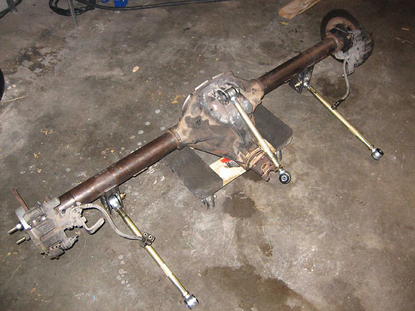
Re: straighline TR8 suspension
|
|
|
|
roverman Art Gertz Winchester, CA. (3188 posts) Registered: 04/24/2009 11:02AM Main British Car: 74' Jensen Healy, 79 Huff. GT 1, 74 MGB Lotus 907,2L |
Re: straighline TR8 suspension
"Maybe" there is room for a longer top link, like Buick Turbo GNX ? I can make billet alum TR8 diff cover with mounting provisions.
|
|
MGBV8 Carl Floyd Kingsport, TN (4629 posts) Registered: 10/23/2007 11:32PM Main British Car: 1979 MGB Buick 215 |
Re: straighline TR8 suspension
Contrary to popular belief, a mount can be welded to the center section.
 Edited 1 time(s). Last edit at 01/31/2019 12:58PM by MGBV8. |
|
roverman Art Gertz Winchester, CA. (3188 posts) Registered: 04/24/2009 11:02AM Main British Car: 74' Jensen Healy, 79 Huff. GT 1, 74 MGB Lotus 907,2L |
Re: straighline TR8 suspension
Welding changes to a rare race car, not good. Not comfy welding cast iron for drag racing. Billet rear cover = no welding.
|
|
|
Sorry, only registered users may post in this forum.
British V8 Home Page
Photo Gallery
Web Forum
Annual Meetings
Contact Info
Site Map
British Race Car

© 2025 British V8™ All rights reserved. Website & graphic design by:
Curtis Jacobson.
BritishV8 Forum is hosted by
SiteWelder LLC,
and is powered by a
Phorum engine.